Testing - 1st Session
Testing 1st Session
Our first session of testing was carried out on the the two Zycomm Sets we are attempting to re-engineer.
We set up a test rig with a dummy load in place of the antenna, with a frequency meter and SR to monitor the transmitted frequency.

 |
Before starting we took a hex dump of each Eprom (temporarily
removed from each Set) using the Arduino reader. We then set about powering up
the Zycomms

The first set we tried [Robin] with the “Neutec” PLL board in it (Motorola MC145146 chip) is transmitting on 77MHz and 72 MHz. This aligns with the Eprom values I grabbed from the set – so far so good.
EPROM READ [ROBIN]
000: 0c 00 0e 0a 01 00 00 03 04 02 01 02 01 00 00 03
010: 0c 01 03 0b 01 00 00 03 0c 00 05 03 01 00 00 03
020: 0e 01 02 0b 01 00 00 03 0e 00 04 03 01 00 00 03
030: 06 01 05 0b 01 00 00 03 06 00 07 03 01 00 00 03
040: 06 02 0d 0a 01 00 00 03 06 01 01 02 01 00 00 03
050: 04 01 0d 0a 01 00 00 03 04 00 01 02 01 00 00 03
060: 02 01 0f 0a 01 00 00 03 02 00 03 02 01 00 00 03
070: 08 01 02 0b 01 00 00 03 08 00 04 03 01 00 00 03
080: ff ff ff ff ff ff ff ff ff ff ff ff ff ff ff ff
090: ff ff ff ff ff ff ff ff ff ff ff ff ff ff ff ff
0a0: ff ff ff ff ff ff ff ff ff ff ff ff ff ff ff ff
0b0: ff ff ff ff ff ff ff ff ff ff ff ff ff ff ff ff
0c0: ff ff ff ff ff ff ff ff ff ff ff ff ff ff ff ff
0d0: ff ff ff ff ff ff ff ff ff ff ff ff ff ff ff ff
0e0: ff ff ff ff ff ff ff ff ff ff ff ff ff ff ff ff
0f0: ff ff ff ff ff ff ff ff ff ff ff ff ff ff ff ff
Tx Frequencies:
CH1 72.4750
CH2 77.3250
CH3 77.0875
CH4 77.7875
CH5 72.3875
CH6 72.2750
CH7 72.7625
CH8 77.0500
The Xtal Oscillator was measured at 4.7999MHz
The Eprom Address clock is 18 kHz
A3 Line on the Eprom is 0v on receive and 3.5v on transmit
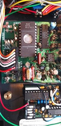
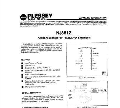
The second set we tested [IAN] was found to be transmitting at around 172 Mhz. the Eprom values were also vastly different. After a bit of puzzling the penny dropped – this second set has got the Plessy NJ8812 equipped board installed – as described in the manual kindly provided initially by Dom.
EPROM READ [IAN]
000: 02 05 07 07 00 0d 0c 0a 01 05 01 08 01 0d 02 0a
010: 00 08 05 08 00 00 00 0b 01 08 0b 07 01 00 06 0a
020: 00 09 0f 07 00 01 0a 0a 02 05 0f 07 01 0d 0a 0a
030: 01 03 0f 07 00 0b 0a 0a 01 05 0f 07 00 0d 0a 0a
040: 01 07 0f 07 00 0f 0a 0a 00 03 00 08 02 03 0a 0a
050: 00 0b 00 08 00 03 0b 0a 00 07 00 08 02 07 0a 0a
060: 00 08 05 08 01 00 06 0a 01 08 0b 07 00 00 00 0b
070: 00 00 08 07 01 00 0c 0a 00 03 08 07 01 03 0c 0a
080: ff ff ff ff ff ff ff ff ff ff ff ff ff ff ff ff
090: ff ff ff ff ff ff ff ff ff ff ff ff ff ff ff ff
0a0: ff ff ff ff ff ff ff ff ff ff ff ff ff ff ff ff
0b0: ff ff ff ff ff ff ff ff ff ff ff ff ff ff ff ff
0c0: ff ff ff ff ff ff ff ff ff ff ff ff ff ff ff ff
0d0: ff ff ff ff ff ff ff ff ff ff ff ff ff ff ff ff
0e0: ff ff ff ff ff ff ff ff ff ff ff ff ff ff ff ff
0f0: ff ff ff ff ff ff ff ff ff ff ff ff ff ff ff ff
So far so good, but we need to understand the second PLL methodology.
Channel Tx Frequency
1 170.1627
2 ~~
3 172.003.
4 167.2002
5 169.0127
6 169.3628
7 169.1377
8 169.1628
9 169.1877
10 169.4377
11 169.5377
12 169.4878
13 167.2002
14 172.0003
15 170.2002
16 170.2378
The Plessy PLL Chip